

Okay, so I’ve been meaning to share this little project I cobbled together. It’s a monitor for the liquid fertilizer setup I use in the garden. Honestly, guessing how much stuff was actually going through the lines was getting old.
Getting Started – Why Bother?
First off, I was just tired of not really knowing. You mix the fertilizer, you turn on the pump, and you hope for the best. But sometimes lines get clogged, or maybe the pump pressure changes. I wanted a way to see, for real, what amount was flowing. Looked at some fancy monitors online, but man, they cost a small fortune. Figured I could probably hack something together myself.
Finding the Bits and Pieces
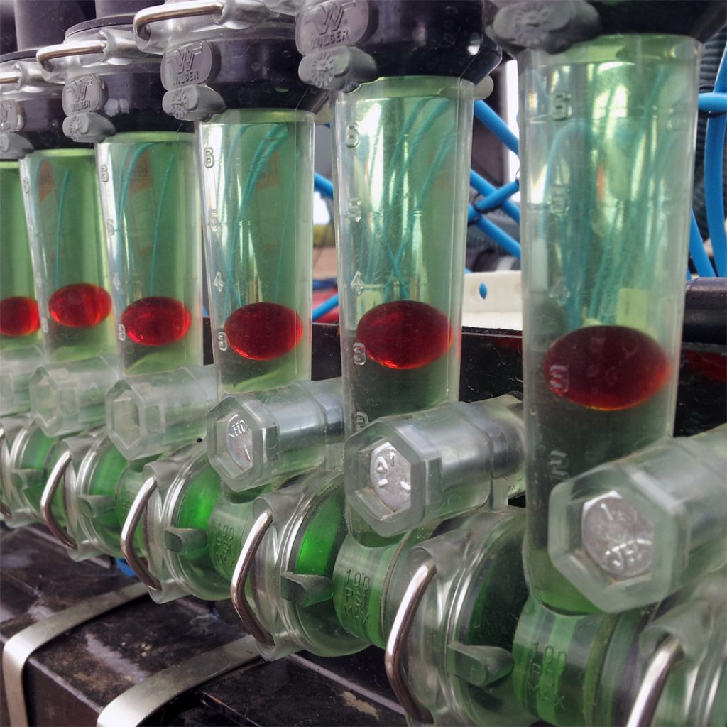
So, the main thing needed was a sensor. I hunted around and found these simple water flow sensors. They basically have a little wheel inside that spins when water goes through, and they send out electrical pulses. The faster the water, the faster the pulses. Seemed straightforward enough.
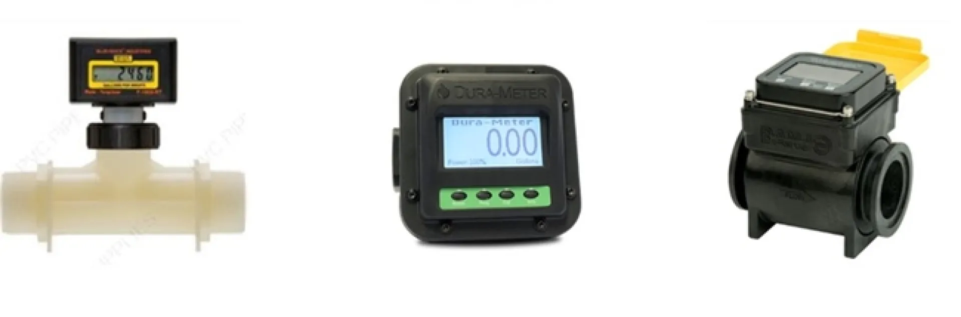
Then I needed something to read those pulses and make sense of them. I grabbed one of those small programmable boards, you know, the kind popular with hobbyists. Cheap and plenty powerful for just counting pulses. Also got a small LCD screen to show the numbers.
- Water flow sensor (picked one suitable for the pipe size)
- A small microcontroller board
- A little LCD display
- Some wires and connectors
- A waterproof box to put the electronics in (important!)
Putting It All Together
This part was a bit fiddly. First, I had to cut into the fertilizer line after the pump and install the flow sensor. Made sure the connections were tight – didn’t want fertilizer leaking everywhere. That took a couple of tries with sealant to get right.
Wiring up the electronics wasn’t too bad. The sensor usually has three wires: power, ground, and signal. Hooked those up to the microcontroller board. Then wired up the LCD screen, which needed a few more connections. I stuffed all the electronics into a plastic project box, drilling holes for the wires and the screen visibility. Tried to make it reasonably water-resistant, you know, for outdoor use.
Making It Work – The Code Part
Okay, the hardware was hooked up, but it didn’t do anything yet. Had to write some simple code for the microcontroller. The basic idea was:
- Listen for the pulses coming from the flow sensor.
- Count how many pulses happen over a certain time (like a second).
- Use the sensor’s specs (they usually tell you pulses per liter or gallon) to convert that count into a flow rate (like liters per minute).
- Display that number on the little LCD screen.
Getting the calculation right took some messing around. The first numbers were way off. I had to do some tests: ran water through the sensor into a measuring jug for exactly one minute, checked the reading on my screen, and then adjusted the numbers in the code until the reading matched what was actually in the jug. Did this a few times to get it reasonably accurate. It’s not lab-grade perfect, but good enough for my garden.
The Final Result
So now, I have this little box zip-tied near my fertilizer tank. When the system’s running, I can just walk over and glance at the screen. It shows me the flow rate in real-time. If the number drops suddenly, I know there might be a clog or the tank’s running low. If it’s zero, well, something’s definitely wrong.
Was it worth the hassle? Yeah, I think so. It wasn’t super complicated, didn’t cost much, and gives me peace of mind. I know the plants are actually getting fed consistently. Plus, it was kind of fun to build it myself. It’s been running for a season now, survived a few rainstorms, seems pretty solid. Gives me actual data instead of just guessing.


